Introduction
I wanted to write something to explain what's done at space research facilities and how electrical engineers can contribute. Most people think space research is a field mostly limited to astrophysics and aerospace engineering, but modern satellites or aircrafts in general heavily rely on embedded systems, custom hardware (usually using FPGAs, and those can be radiation-tolerant), fault-tolerant digital systems and real-time operating systems. On top of that, modern satellites also integrate their power systems, extremeley complex wireless communication systems and state of the art solar panels.
I was extremely lucky to intern at the Brazilian National Institute for Space Research, it is one of the best research intitutes in the entire southern hemisphere and I'm sure anyone who likes digital systems would have a blast there. You can see several space systems in development and the technology is simply fascinating.
The Brazilian National Institute for Space Research
I could write a few paragraphs talking about the institute itself, but I feel like that would be reasonably out of scope and perhaps a waste of time since INPE itself has a page dedicated to its history.
Most have probably heard of INPE when the Amazon fires happened in 2019. The institute was responsible for monitoring the jungle and reporting deforestation numbers. The Amazon covers a very large piece of land, and at 5.5 million km² it is larger than the entire European Union (4.476 million km²). Monitoring the entire land requires technical expertise and an entire constellation of satellites.
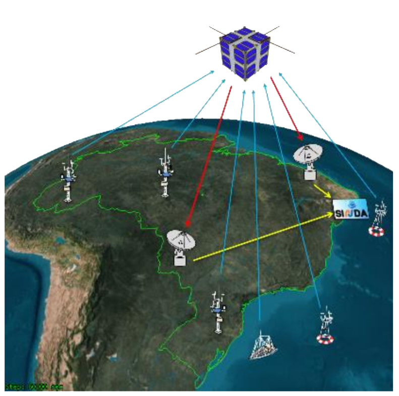
Conventional satellites are usually bulky and expensive to build and launch, those factors created a problematic barrier that keept innovation away from space due to monetary costs. In recent times, however, we've seen most agencies slowly migrate to small nanosatellites, CubeSats.
During my internship, we worked on an environmental data collector. To be more precise, we worked on a ARGOS PTT-A2 CubeSat-compatible decoder payload.
CubeSats
Before getting into details, it's important to describe what a CubeSat is.
A CubeSat is defined as compact small satellite composed of 10 cm x 10 cm x 11.35 cm 1.33 kg cubes. Usually speaking, CubeSats also tend to contain off-the-shelf components to decrease costs. The initial specifications were published in 1999 by California Polytechnic State University and Stanford University to promote and expand the knowledge realted to designing and manufacturing cheap low-orbit satellites.
Recently, the Federal University of Santa Catarina launched their first CubeSat, FloripaSat-1, a successful mission of extreme importance to the aerospace field in Brazil. FloripaSat-2, its next iteration, is scheduled to integrate the EDC, which is the project I worked on.
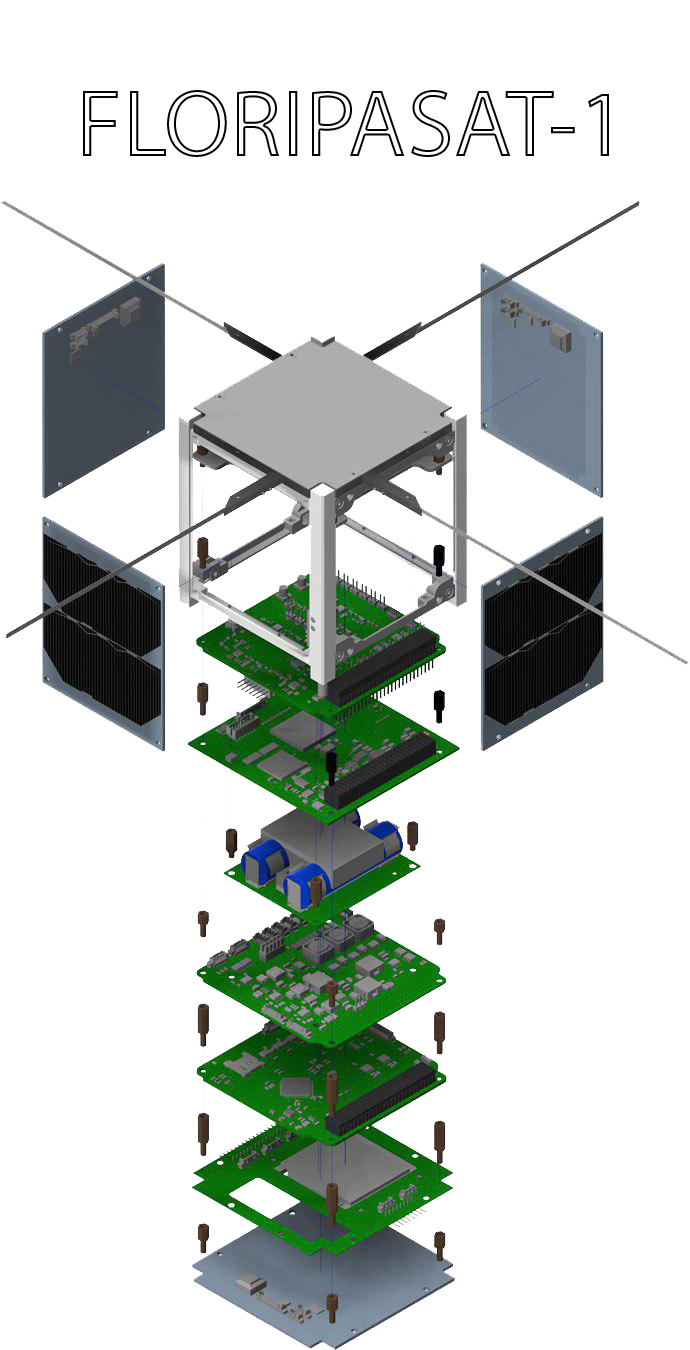
Our payload, shortened as "EDC" from Environmental Data Collector, is designed to detect and decode signals coming from remote terrestrial platforms. INPE adopted the ARGUS PTT-A2 standard, which was developed by France and the US to monitor wildlife, the environment and marine activity.
The ARGOS system has been used since 1978 in various programmes like "Tropical Ocean-Global Atmosphere program (TOGA)", "Tagging of Pacific Pelagics (TOPP)" and "World Ocean Circulation Experiment (WOCE)" to name a few. Nowadays, more than 100 countries utilise the same system in a way or another. The Centre National D’Etudes Spatiales (CNES) recommends that PTT-A2 signals should be transmitted within the 401.620 MHz to 401.680 MHz band, but excluding the portion dedicated to the ARGUS-1 system, 401.646 MHz to 401.654 MHz.
Our payload, the EDC, has a radiofrequency front-end capable of detecting PTT-A2 signals present in the 401.635 MHz ± 30 kHz band with receiving power between -128 dBm and -98 dBm.
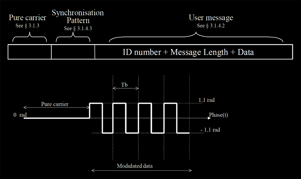
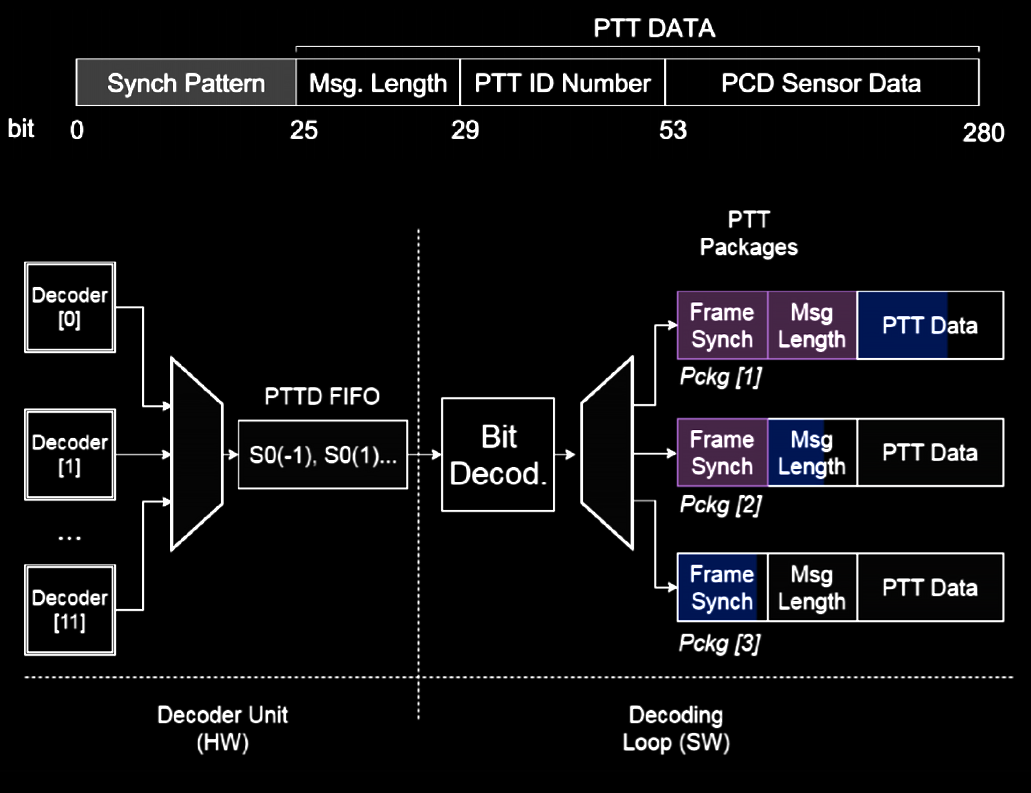
PTT-A2 signals are relatively simple, they're initially carrier-only to simplify detection. Then, the data is transmitted through a simple PSK modulation of 2 symbols. A positive symbol transition equals to a logical level 1, and a negative transition is a logical level 0. The message comes structured in the following manner, first a synchronisation word needs to be decoded, then the length of the user message is then presented, followed then by its ID and then by the actual message.
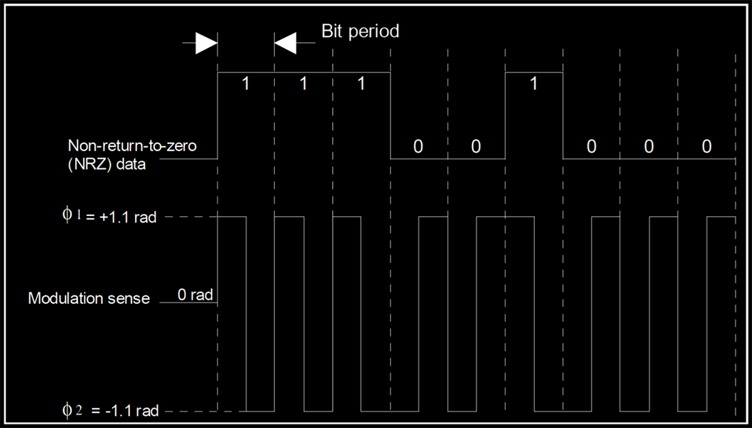
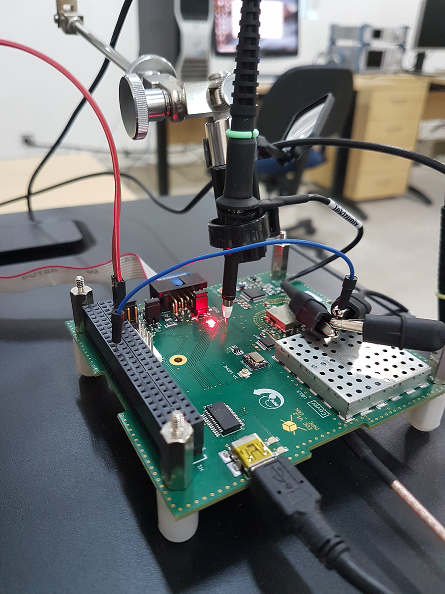
The hardware is capable of decoding up to 12 signals simultaneously. This is possible because there are 12 parallel decoders synthesised in the Microsemi SmartFusion 2 FPGA.
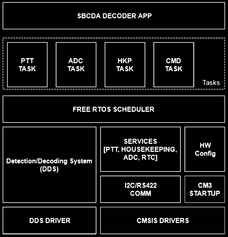
The EDC was also able to be remotely configured by an on-board computer, offering I²C and UART interfaces for communication.
To be more detailed, the EDC basically presents itself to the on-board computer as a slave. It has multiple tasks that can be called through several commands, with services responsible for providing the data to be transmitted to the OBC. The software responsible for answering the OBC runs on top of FreeRTOS on a ARM Cortex-M3, since it allows us to more easily add tasks to the payload.
The EDC Testbench
As an intern, my primary activity was developing a way of testing the prototype. The testbench included an x86 workstation running Matlab, an Arduino Due and a Rohde&Schwarz SMB100A signal vector generator. Matlab was used as a HIL orchestrator, emulating both the on-board computer through the Arduino Due (which was used to make a USB -> I²C bridge) and incoming signals controlling the SMB100A through TCP/IP.
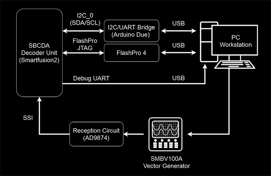
Matlab was chosen due to convenience it brings, since you can easily control all instruments with a single script. It's also important to note that we didn't even need the instrumentation toolbox, baseline Matlab already had access to the Arduino libraries and we could control the Rohde&Schwarz instrument using simple ASCII SCPI commands.
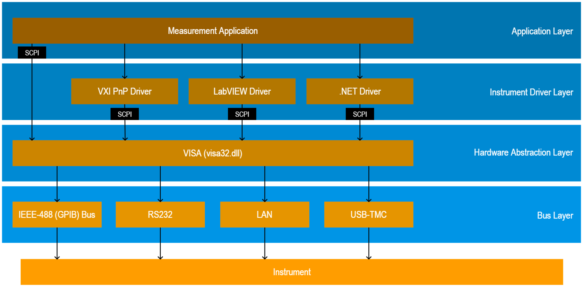
Testing was done through re-creating real-world scenarios and observing how the prototype behaved, which signals it was able to decode properly, which corner case situations revealed bugs in our firmware, how it handled weird OBC behaviours, etc.
Examples that can be easily given include testing for different input power levels, different number of concurret signals (the EDC is supposed to be able to decode up to 12 signals simultaneously), different carrier frequencies, etc.
We had several problems, which includes several things like the OBC simulation (causing the interrupt controller to stop working when interrupted too quickly), or sometimes being able to detect and decode unintended nearby signals even without using a proper antenna (the radiation was enough, since the system is made to work in space several hundred kilometres away from the surface), having insanely weird results due to using PWM voltage converters and even endianness issues when communicating with big-endian devices.
Unknown to us, some I²C implementations also limit the maximum message length. Our prototype had 2 frames that were too big for the Arduino Wire library, the ADC Frame (simply a bunch of samples from the analog front-end) and the PTT Frame (which contained several informations like signal power, frequency, its ID and decoded data).
By default, Wire only allows transactions (I²C reads or writes) of up to 32 Bytes at a time. We assumed that this could be a problem with an arbitrary on-board computer too and decide to implement a workaround, simply breaking packets into smaller ones and introducing an addressable pointer. The result is very simple, large parckets can be retrieved through a series of I²C reads.
Closing Thoughts
I think I can easily conclude that my time spent at INPE/CRN was amazing. I've learnt many things and I could also work with what I've always loved, hardware. The experience exposed me to a different "market", and I found out that space applications require their own domain-specific microcontrollers due to a series of fault tolerance requirements. The LEON SPARC cores are reasonably popular but we've seen a push to bring RISC-V to space, specially by Microsemi and their Mi-V ecosystem.
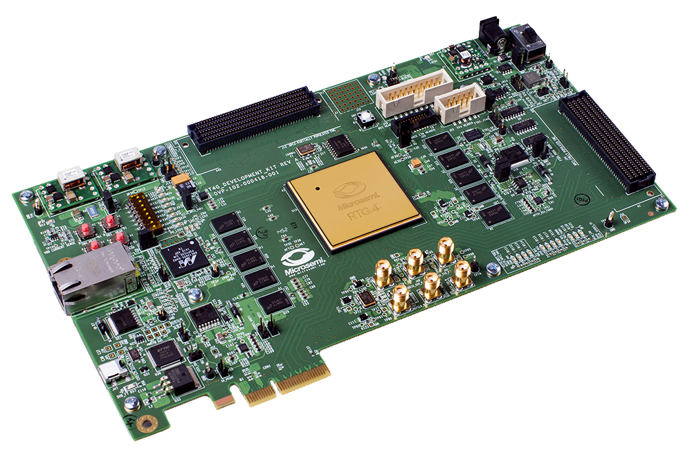
As someone who advocates in favour of open hardware, the openness of RISC-V makes it incredibly convenient for the space market, since we have a range of successful open-source projects that can be modified for fault tolerance, like Rocket, BOOM and PULP.